Building the “perfect” MEMS mirror for next-generation lidar – what have we learned?
By Ewan Laidlaw
Earlier this year, we challenged ourselves to design a “perfect” beam steering unit for next-generation lidar. Here we discuss what the experiment has taught us about perfecting the design of a MEMS mirror for lidar.
In our previous blogpost, we highlighted MEMS mirrors as the most plausible beam steering solution for second-generation lidar sensors because they are robust, can be cheap to manufacture and, most importantly, offer unrivalled design flexibility.
The “perfect” MEMS mirror, we argued, will look different depending on the other sub-systems in the lidar sensor. The challenge, therefore, is to design and optimise a beam steering unit that meets the requirements of a particular lidar system. And the ability to do this can alleviate development headaches by removing constraints on other sensor sub-systems.
In this vein, we then set out to design several torsional, electromagnetically driven MEMS mirrors that would satisfy automotive lidar requirements for resonant frequency and field of view (FOV).
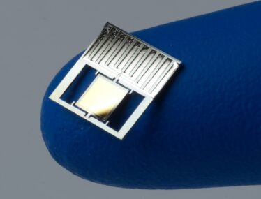
We used multiphysics simulations to undertake the detailed design and modelling work for a range of mirror geometries. These units were then manufactured in an in-house microfabrication facility.
In this blog, we discuss the results we achieved, some of the unexpected physical behaviour we encountered, and what the experiment teaches us about perfecting the design of a lidar beam steering unit.
Validating the MEMS mirrors
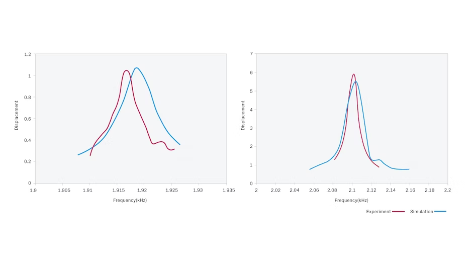
We tested the MEMS mirror units optically to experimentally validate their resonant frequency and measure the mirror displacement for a range of drive currents. We also measured the full resonant curve for the mirrors – i.e., displacement versus excitation frequency – which allows us to understand other critical parameters of the units.
The optical test video (below) shows the expected sinusoidal “wobble” of the mirror, as well as the oscillating laser spot, and our experimental results compare well to our models.
The resonant frequency of the mirrors matched our modelling extremely favourably – within 0.2%. This highlights the ability to design beam steering units of a range of sizes for critical design parameters such as resonant frequency. At low currents, the mirrors’ maximum angular displacement also agreed well with the mathematical models (Figures 1a and b).
Extending the underlying theory for MEMS mirror beam steering units
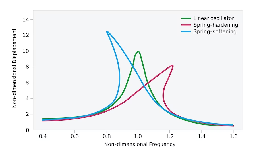
When we started to push the limits of mirror motion by ramping up the driving current, the increase in the maximum mirror displacement became non-linear (cf. blue experimental line in Figure 3). This challenged our models – as non-linear problems tend to – so we decided to delve into the underlying theory as a quicker route to understanding the physics behind the behaviour of our MEMS mirrors.
Since, at higher currents, the MEMS mirrors no longer behaved as a linear oscillator – described by basic theory and where the only variables are mass, stiffness and damping – the extension to this theory assumes an additional, non-linear stiffness term.
This term causes phenomena such as “spring-hardening,” whereby the normally straight up resonance peak tilts towards higher frequencies at large deflections (Figure 2) – as we also observed in our experiments.
This behaviour would limit the FOV of a beam steering unit, because where the curve tips over the function becomes multi-valued and unstable. This instability almost always favours the lowest energy value and thus the smaller of the possible displacements. This non-linear behaviour has also been reported in the literature.
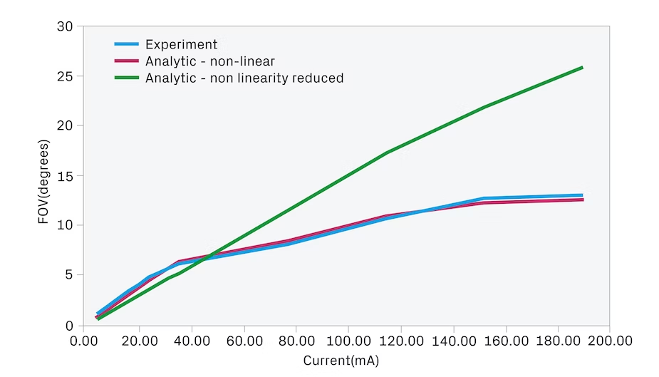
The good news is that with our extension to the theory we were able to account for the non-linear behaviour of our MEMS mirrors. The analytic solution to the more complex non-linear equation nearly perfectly predicted the maximum angular deflection achieved at each driving current (cf. Figure 3), confirming that “spring-hardening” was indeed causing the non-linear behaviour.
We are confident from our understanding of where the non-linear term has been introduced that such non-linear behaviour could be avoided by design in future. The yellow line in Figure 3 illustrates the FOV that could be expected for MEMS mirror beam steering unit as a function of driving current (up to the maximum used in our experiments) if non-linearity was reduced by design.
Other insights: Support, magnetic structures, and materials
Another area for learning concerns the design of the support structures for MEMS mirrors – i.e., how to hold them in position, how to electrically connect to and control them and how to provide the magnetic field for electromagnetic driving. Getting all of these right is just as important for performance of a beam steering unit as getting the silicon MEMS part designed and fabricated well.
For example, the magnetic structures within a beam steering unit are critical because a stronger magnetic field for the same driving current will create a larger driving force and, ultimately, FOV. Optimising the magnetic field may not just be valuable for improving system performance but critical for achieving the required performance.
In the MEMS mirror units we built, the magnets were simple to allow the prototype to work robustly. But we also came up with other, more complex designs that could improve FOV as well as providing benefits during mass manufacture. Furthermore, as the support structures are generally going to be custom-designed for each MEMS mirror, this is potentially a rich area for innovation and IP in MEMS devices.
The exercise has also given us new ideas for materials for MEMS beam steering units. Advantages may be found by combining materials and processes going beyond pure silicon MEMS manufacturing. For example, some lidar sensors use metal mirrors, which present their own advantages and challenges. We could go further and combine different materials – enabled by a fundamental understanding of the technology – to produce exciting new designs with new advantages.
So, what have we learned from setting ourselves this challenge? The MEMS mirror units we designed and manufactured work as expected and have given us important insights and new ideas for the design of lidar beam steering units. The “perfect” MEMS mirror is within reach and can be tailored for integration into a wide range of lidar sensors.
TTP offers extensive experience in the development of low-cost sensors now also to the autonomous driving industry. Please contact us to learn more about our MEMS mirror design activity, or for any other automotive sensing requirement.